This Lasercutter is -more or less- a copy of the cutter constructed at hackerspace Bitlair*, Amersfoort, NL.
Eightdot* started this copy for Hack42, Arnhem, NL, around 2014, but due to personal circumstances he was not able to finish the job.
Early 2019 JanBee* started to finish it, taking a lot of advises and suggestions for improvements from HobbyBob* (HB) and Eightdot* into account.
An important design criterium for this machine was to allow materials of size 1220 x 610 mm to be handled. This is (at least in NL) a standard dimension of widely available materials such as plywood.
This documentation is primarely meant to maintain the machine at Hack42.
It is NOT an instructable to build a Laser Cutter, but those who are involved or are planning to build one may profit from the information here.
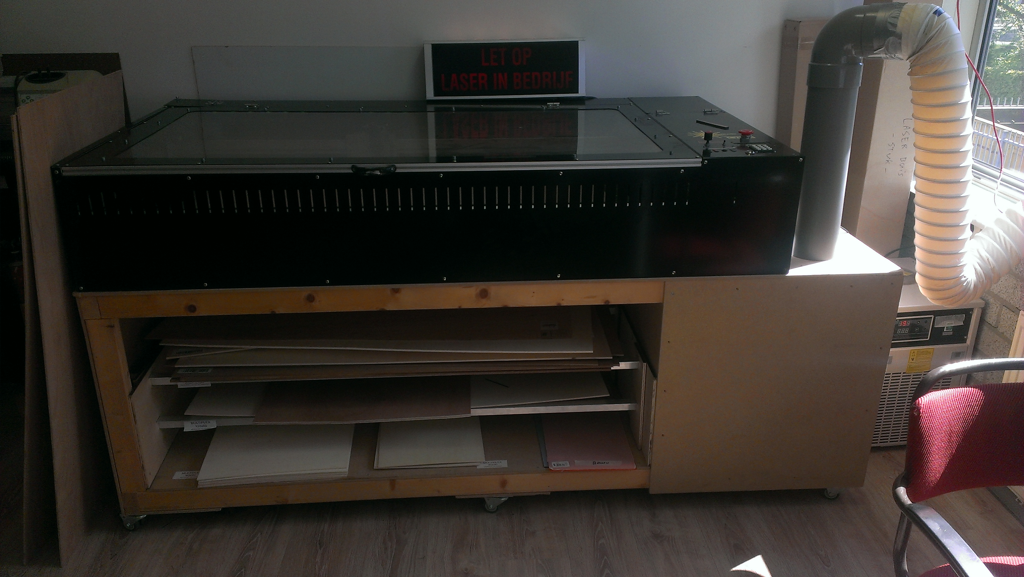
The LaserCutter at Bitlair, Amersfoort, NL.
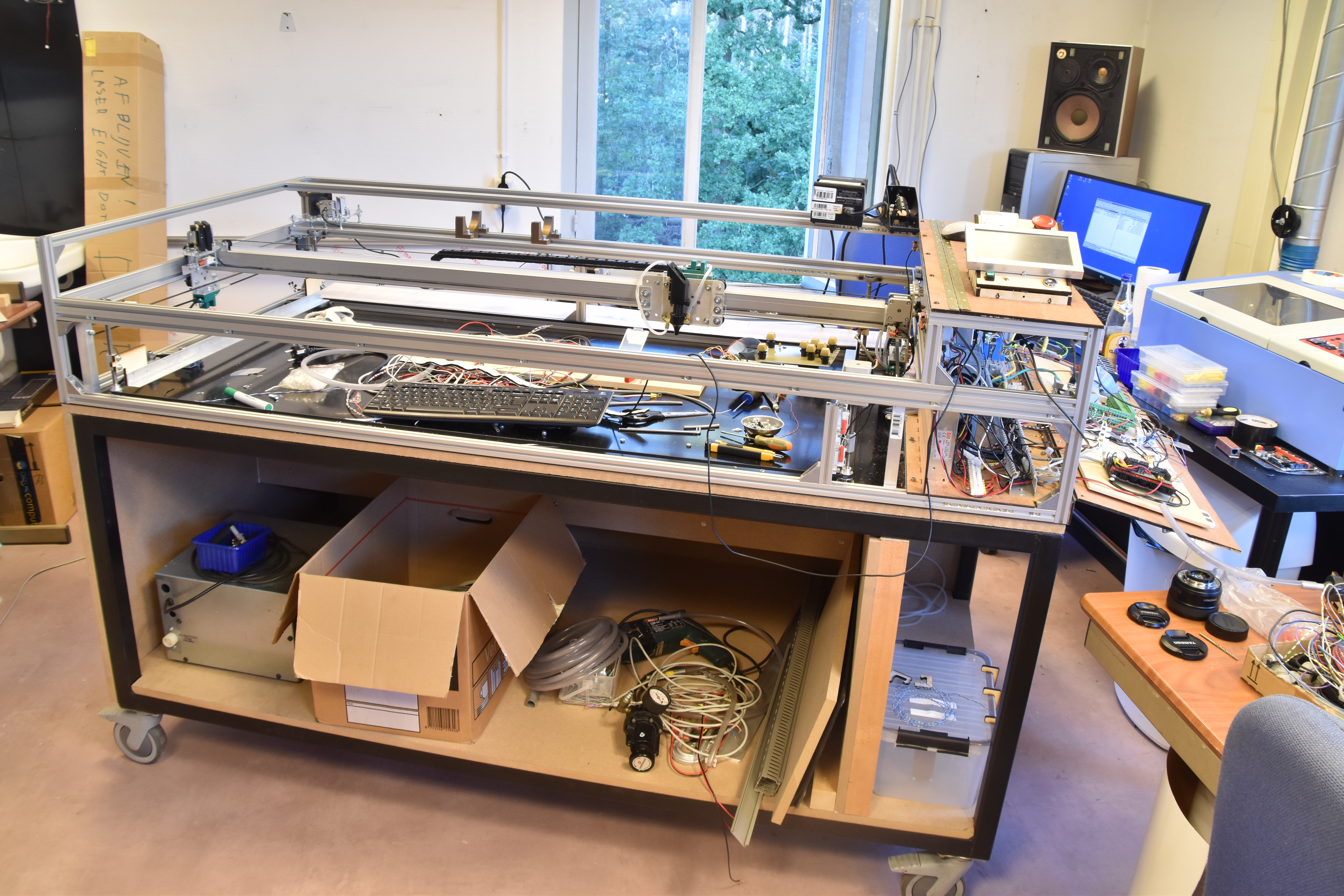
The "FatMan" under construction at Hack42. (Photo 2019-07-23)
To the very right, partially visible the smaller laser cutter "Little Boy".
It was very helpfull to have a smaller working laser cutter at hand (kind of K40-clone) so we could make many smal parts from either plywood or polyacryl. Also we are in the lucky position to have a metal workshop with a lathe and a milling/drilling machine with accurate X-Y-Z positioning. This made it possible to make several parts from metal, mostly aluminium, in stead of 3D-printing which gives less sturdy parts.
When I (JanBee) started to work on this machine early 2019 most of the parts were present; the frame was mounted, the X- and Y motors and drive belts were mounted, the cover could be opened and closed and several panels of either metal or plywood were present. There were Power supplies and motor drives and even a Laser Tube specified for 100 Watt optical output.
Advised by HB* and EightDot* we decided to implement a number of improvements over the Bitlair unit.
Support Construction
The frame of the machine itself is not stiff enough, it needs support of a very rigid and stable structure. We constructed a frame from welded 40 x 40 x 2 mm square steel tubes, the whole thing on wheels. The frame is dressed with some 18 mm thick MDF plates, on top, bottom, backside, left and right side, leaving space for storage of materials and on the right side the cooling system.
Integrated in this MDF construction is the exhaust fan which sucks air from the laser space and blows it out of the building through some large diameter hoses.
See more....
X-Axis
HB* advised us to mount the X-motor and the return pully on the X-beam itself, and not on the endplates which carry the Y-wheels. This prevents the endplates to bend in response of the X-movements, de-alineating mirror 2.
Also we kept the drivebelt connection as low as possible to prevent wobbling of the mirror-3 plate.
The beam of the X-rails has been reinforced in the Y-plane with a 25 x 25 x 2 mm “U” profile over nearly the full length. This profile is also used to guide the X-caterpillar.
See more....
Y-Axis
In the original design the drive of the Y-axis was done by the motor at the back-center side, with two M5 threaded rods to the sides where two dented belts were driving the X-beam. We replaced these M5 rods by 10 mm aluminium tubes. Some lath-work was done to interface the tube to the 5 mm rods carrying the Y-pullies and the motor axis.
See more....
Z-Axis
We choose to implement a laser bed which can be motorically adjusted in height, to adapt to different thichknesses of materials or workpieces. The bed is now supported by 4 M10-threaded rods which end in bearings and pullies. A closed belt drives the 4 pullies synchronically. 1 of the rods is directly driven by the Z-motor. End switches limit the travel of the bed.
See more....
New Tensioners
BugBlue* designed new tensioners for the X- and Y drive belts.
See more....
Bed
The surface on which materials to be cut or engraved can rest is the usual honycomb structure. The honycomb is supported by aluminium L profiles 25 x 25 x 2 mm positioned with the hypothenusa in the horizontal plane. The frame of the bed rests on the L-profiles of the Z-axis mechanism and can easily be taken out to clean the area below. It can be replaced at exactly the original position by a few notches.
See more....
Winch / Cover
We decided to implement a motor driven winch to open and close the cover of the machine. The size of the cover is such that people of moderate size find it difficult to open or close it.
The frame of the machine was modified such that the opening on the front of the bed area is now lower, making the placement of materials easier. The corresponding part on the cover is provided with slits to allow air from the room to enter the bed-area, but in such a way that (laser) light cannot go through there. The front plate of the cover has a little overlap such that no laser light can go through the slit.
See more....
Exhaust
In the original design the exhaust was on the right side of the channel below te lasertube. This causes a sub-optimal airflow over and below the laserbed. In the new design the exhaust fan is below the table top, in the middle of the laser area, and sucks over the full width of that area.
See more....
Optics
During the construction we had a small He-Ne laser available which was mounted on the place where the CO2 tube should come. With this visible light most of the mirror adjustments were done. Doing so the CO2 laser tube needs to be mounted only in a very late stadium of the whole construction process and there is less need for adjustment-shooting with the CO2 tube.
See more....
Mounting the Laser Tube
The 3-D printed mounts which were already made allowed adjustment in the horizontal plane, but not in height. The commercially available mounts for a 80mm diameter laser tube were to heigh, they would not fit into the machine. We designed some mounting plates allowing vertical adjustment of the tube.
See more....
Pilot Light
We decided to implement a red LED-laser based pilot light, to help adjusting workpieces on the bed.
The Beam Combiner stuff we bought throug the AliExpress channel did not have enough adjustment possibilities, so it was modified in several ways. Basically two independent adjustments are required: First to aim the pilot laser such that it hits the combiner mirror exactly at the place where the CO2 beam leaves this mirror (should be the center of the mirror), secondly to adjust the combiner mirror such that the pilot beam is exacltly aligned with the CO2 beam.
Also it was positioned in a non-perpendicular way to have more margin for the CO2 beam width.
See more....
Mirror Adjustments
The usual mirror mounts have adjustment facilities only for rotating the mirror in the horizontal and vertical planes. However also adjustments for translation in X, Y and Height are required to have the beam hit the mirrors in their center. We realized this by mounting the mirror-mounts on laser-cut acryl plates which allow adjustment in X, Y and Z directions by adjusting nuts on M5 threaded rods through 5.2 mm wide slits.
See more....
Electronics
The safety facilties of the usual laser control boards (we chosed fort he Smoothie Board because it supports fast streaming of raster data) are quite marginal. Advised by HB* we implemented a “Safety Board” (SFB) which monitors and controls most of the functions in the machine and tells the Smoothie Board (SMB) with a few signals that all is safe, job can be started/paused/stopped, etc. The SFB talks by ETH/UDP with the RaspberryPi which runs the GUI displaying data and allowing control on a 7-inch touch display.
See more....
Smoothie Board
We use a Smoothie Board V1.3 from BigTreeTech. A special interface board was created to route signals from / to the Safety Board (SFB). The SMB talks with the LaserWeb Server running on the Raspberry-Pi (Pi) through the serial port on the Pi's GPIO connector.
See more....
Laser Interface
A functional description of the interfacing with the HVPSU.
See more....
Safety Board
The Safety Board (SFB) monitors and controls most of the functions in the machine. It listens along with the signals sent by SMB to the HVPSU, with Home and Endswitches etc. It measures water flow and temperatures. The SFB is a quite dumb board, it measures and controls, but most decisions are made in the GUI program running on the Pi
See more....
Crydom Board
The Crydom board hosts up to 8 solid state switches. It is used to switch mains power under software control to several sub-units.
See more....
Winch
A motorized winch is implemented to open and close the cover. The open / close commands are given through a serial connection between the SFB and the Winch Control Board (WCB). Commands originate from the GUI on the Pi.
See more....
Cooling System
Cooling the laser tube is extremely important. When operated at the specified maximum output power the tube dissipates around 450 Watt. The tube is designed to use water cooling. Optimal temperature for the tube is around 17 °C, which is generally lower than room temperature. So passive cooling by air is insufficient, an active cooling system is a must. A second thing is that we must prevent a temperature shock for the laser tube when the system is switched on.
See more....
Water Quality
The water flowing through the laser tube must have a very low electric conductivity, otherwise there is a risk of flashing at the high-voltage side of the tube. This can be achieved by using destilled water. There is discussion in the laser community whether to use demineralized (DM) or destilled (DS) water. Well, the difference is that DM water may contain non-ionic contaminants on which algea might grow. Destilled water surely is free of such contaminants. Both may absorb gasses from the air, in particular CO2, which makes the water slightly acidic, and so conducting. Also metals might dissolve a bit.
We use destilled water with addition of a little anti-algea solution, and we continually monitor the conductivity of the water.
See more....
Air Assist
The AirAssist is a nozzle from which air is blown onto the cutting place.
See more....
*Legend:
Bitlair: Hackerspace in Amersfoort, NL.
Bugblue: A participant of Hack42.
Drive Power: The part of power circuits that must be explicitely switched on, and will be switched off by the Emergency Button.
EightDot: Participant of both Bitlair and Hack42 who initiated the construction of the Hack42 Lased Cutter.
FatMan: The name we (#42) gave this machine. In contrast with the smaller laser cutter named Little Boy.
n.b. Little Boy and Fat Man were the names of the atom bombs on Japan in 1944.
Fpc / Lazarus: Free Pascal and the Lazarus IDE (Integrated Development Environment) to make programs with a GUI, Graphical User Interface.
Lazarus / FPC is freely available for many platforms, Wxx, Mac, Linux, Raspberry Pi, etc. The slogan is “Write Once, Compile Everywhere”.
This is true for the larger part, but running an application on different platforms can give supprisingly different cosmetic results.
GUI: Graphical User Interface. Something like Windows on a screen.
Hack42, #42: Hackerspace in Arnhem, NL. Location of this Laser Cutter.
HB: HobbyBob, participant of Bitlair having much experience with buiding laser cutters.
HVPSU: High Voltage Power Supply Unit for the CO2 laser.
JanBee: A participant of Hack42 who is finishing the Laser Cutter and made the (this) documentation.
MDF: A cheap plate material consisting of fine wood grains and a lot of of binding material. Available in a range of thickness.
Pi: the Raspberry Pi which runs the LaserWeb-server and the LaserControl-GUI.
SFB: Safety Board.
SMB: Smoothie Board.
WCB: Winch Control Board.
Winch, Winch Controller:Mechanism for motor-driven opening and closing the cover of the machine.